
Build Your Own Blackout Comms
Getting Started with Lilygo or Heltec
Get a private secure mesh cluster up and running with nothing more than a couple of Lilygo T-Deck or Heltec devices! You can easily add more devices & capabilities later on.

1. Get Some Devices

Get 2 or more communicators: any combination of T-Deck, T-Deck Plus, Pager, or Heltec V4 Exp Kit
2. Add Compatible SD Cards
Not required, but recommended for T-Deck+ and Pagers. A good option from Amazon is this PNY card.
Adding an SD card makes it easy to switch between devices (like a SIM card).
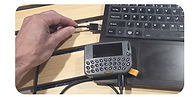
3. Install Blackout Comms Firmware
-
Each device in your cluster needs Blackout Comms firmware. (This takes about a minute)
-
Lastly, you’ll need to onboard them to your new cluster.
Add Links (Optional)

Extend your cluster and add GPS trackers. Many good options are available, see the full compatible device list or the DIY guides.

If you install Blackout Comms firmware to any mesh link/node, it is immediately ready to onboard at startup.
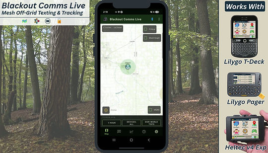
Blackout Comms Live App (Optional)
-
Track devices in real time
-
Download maps for fully offline & off-grid use
-
Send/receive secure broadcasts & direct messages
-
See cluster-wide connectivity
-
Monitor your mesh cluster's load and performance
You can use nearly any Android phone or tablet with any compatible Blackout Comms device.
Other Supported Devices
There are some great and inexpensive options for building your own devices. If you buy from us, everything is fully assembled, flashed with Blackout Comms, licensed and ready to run. If you build it yourself, we can't help if you run into hardware issues.
Communicator Hardware Options
Compatible SD cards are highly recommended for communicators, for easy backup and longevity.
Custom T-Deck
The absolute best, but quite a DIY project


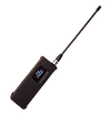
Link / Node Hardware Options
Currently the T-Beam Supreme and Heltec e290 are the recommended options for DIY. T-Beam Supreme only requires adding a battery and enclosure, while the e290 has more options and a much better display (but requires additional components & soldering).
Lilygo T-Beam Supreme

Easiest option - good performance
Heltec Vision Master e290

Excellent - top performer

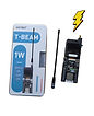
Lilygo T-Beam 1W
Lots of Power

Lilygo T3S3 ePaper
Nice screen - MQTT not supported

Full DIY - Build & Customize
These builds are more challenging, but I try to make them as easy as possible. A custom PCB (you can get from me or PCBWay) has instructions printed on it. Basically, solder the components into place and drop into a 3D printed case.

